


Arduino Nano as IR sender and receiver
| Date | Description |
|---|---|
| 2016-01-08 | Initial version. |
| 2016-02-10 | Fixed some broken links. Uploaded some missing pics. |
| 2020-04-21 | Minor updates of the things changed during last four years. |
Introduction
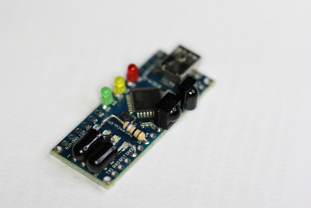
In this article, we present a simple, yet quite powerful, microprocessor-based IR sender and receiver as a do-it-yourself project. It is particularly geared towards IrScrutinizer and Lirc, but other usages are also possible.
As presented here, there are components for IR transmission, demodulated- and non-demodulated IR reception, and signaling LEDs. All of these are optional.
For the ease of assembly, components are soldered directly to the holes of the PCB. For pins that should be connected to ground or to +5V, these are sometimes GPIO pins, which in software are assigned a constant LOW or HIGH level.
The current article is aimed at beginners. As a DIY project, it can be considered "simple to medium" on a scale from very simple to very hard. Elementary experience with soldering of electronic components is assumed, as well as installation of system components in Windows or Linux. It is also necessary to be able to program the flash memory of the Arduino with its the Arduino IDE. However, no programming knowledge is required.
The price for the components is around 8 EUR or 9 USD.
There is a second part of this article, covering some details that, for easy accessibility by inexperienced readers, were left out of the current work.
Component selection
For the ease of reading, this section is written without mentioning alternatives. These are instead discussed in the second part. For the same reason, links to data sheets for the mentioned components is found only in that part.
The appendix contains the complete bill of materials.
Processor board
As processor board, we select an Arduino Nano-clone (Version 3.0 or 3.1). These can be purchased e.g. on Ebay for a very low price (< 3 EUR) from Asian manufacturers. To be useful for us, it should come with a mini-USB socket, and with bare holes (i.e. without pins) at the sides, see the photos. It should also be equipped with an ATmega328 5V, but that appears to hold for everything currently offered.
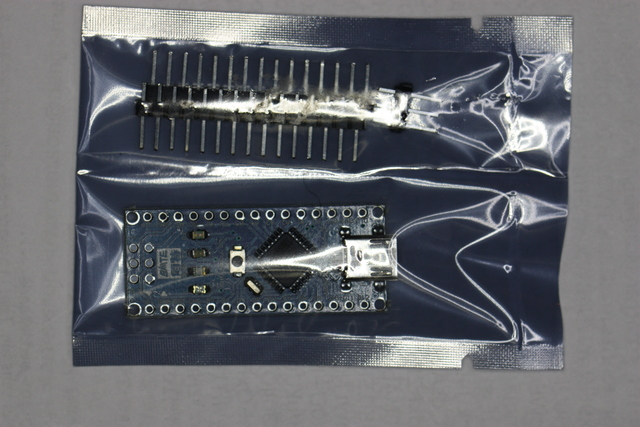
The Arduino Nano clone as delivered in an anti-static bag. The solder pins in the upper part of the packing are not needed, and can be disposed.
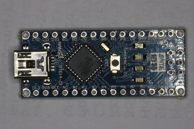
The board unpacked. Note the mini USB connector to the left.
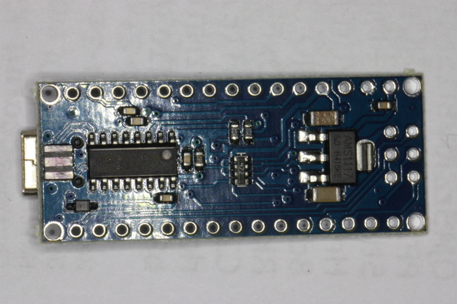
The same board from below.
All of the following components are optional, and can be left out if a certain functionality is not desired. Nevertheless, I recommend incorporating all. The components are really not that expensive.
IR sending diodes
For maximal sending performance, we use one IR LED with narrow beam together with one with wider beam, thus combining the advantages. We select the Osram SFH4544 and SFH4546. These are connected in serial, together with a 68 ohm resistor. If sending is not required, these can be left out.
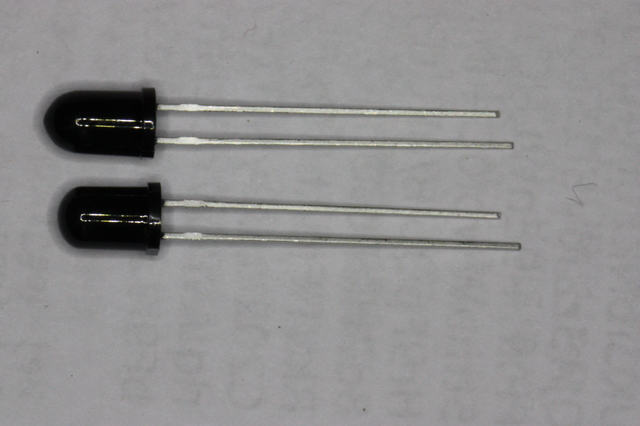
The IR LEDs before assembly. It can be seen that the SFH4544 has a slightly longer housing than the SFH4546. Also note that, as opposed to most other LEDs, the cathode pin is the longer one.
Non-demodulating sensor
This allows for very accurate measurements of a possibly completely unknown IR signal, including measurement of the modulation frequency. This use case is called capturing or learning. It is not well suited for deployment reception of IR signals, for example in the context of Lirc. (Lirc cannot use this sensor.) We select the Vishay TSMP58000.
Demodulating Receiver
This is meant for deployment reception of known IR signals, allowing reception over a very long distance. This use case is called reception. It is not very well suited for "learning". We select the Vishay TSOP34438.
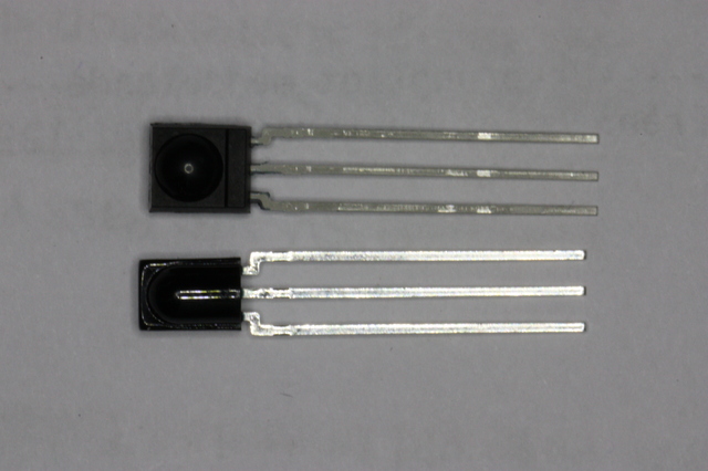
The demodulating sensor TSOP34438 (top) and the non-demodulating sensor TSMP58000 (bottom).
LEDs (for visible light)
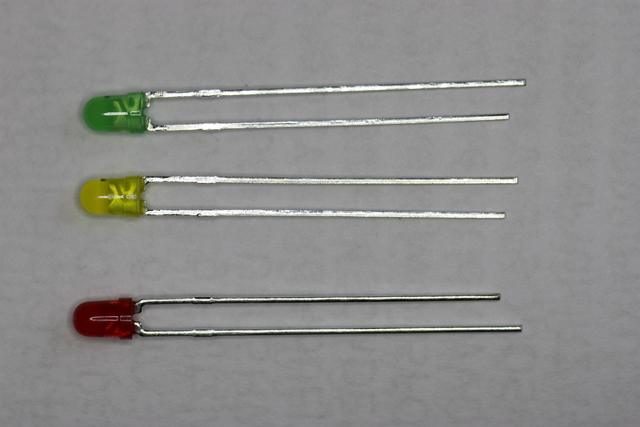
LEDs must always be connected using series resistors. Since discrete resistors would increase the component count, and thus the assembly difficulty, instead we use LEDs with built-in resistors. The 3mm 5V LEDs from Kingbright fit perfectly into the Arduino holes, and are not very much more expensive than normal LEDs. They are available in red (WP710A10ID5V), yellow (WP710A10YD5V), and green (WP710A10SGD5V); unfortunately not in other colors.
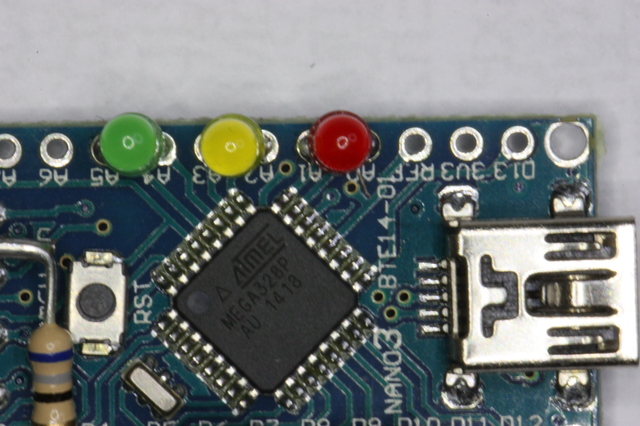
Here, we use a red LED as the first one, a yellow one as second, and a green one as third.
These are purely for signaling and debugging purposes, and can be left out without any functional penalty.
Assembly
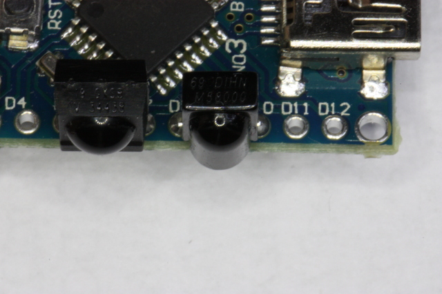
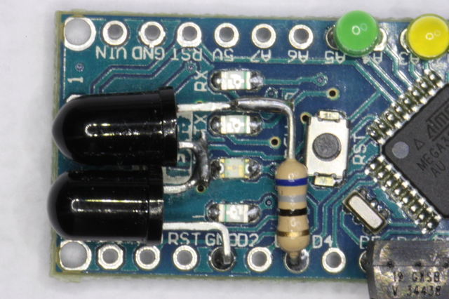
The TSMP58000 goes to the holes D8, D9, and D10; the lense facing outwards (see pictures). Likewise the TSOP34438 goes into pins D5, D6, and D7.
Then, the red LED is soldered to pins A0 and A1. Unfortunately, there is no marking on the housing indicating anode or cathode. Instead, the cathode is the shorter pin, and should go to A0. Likewise, the yellow LED go to pin A2 (shorter pin/cathode) and A3. The green LED go to pin A4 (cathode/short) and A5.
The IR LEDs are slightly harder: The cathode of one (does not matter which) should be connected to the "GND" hole, the forth hole from the right in the upper row (assuming that the mini-USB connector points to the left). Then the anode should be connected to the cathode of the other one. Finally, the anode of the other one should be connected through the resistor to pin D3. On the Osram IR LEDs, the cathode is marked by a flat area on the housing. Here is obviously room for some creativity. Consider my pictures as a suggestion only.
Drivers etc
To be used by any program, the device has to be recognized by the operating system by a driver. On Windows, it will be available as a COM device, like COM12 or such, on Linux and MacOSX a device like /dev/ttyXXXX, acting like a serial device.
Windows
While the original Nanos use FTDI FT232RL for serial communication, and should be used with FTDI drivers, this is both technically and legally not possible or not feasible for the clones, which instead use a CH340 chip.
My Windows 10 system identifies these boards automagically as USB-Serial CH340 in the device manager, see the screen-shot below. Using other versions of Windows, it may be necessary to download and install a CH340 driver manually.
The device shows up in the device manager as in the following screen shot (marked yellow):
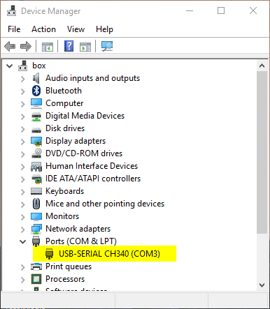
Note the device name that the Windows has assigned to it, here COM3.
MacOS X
This is presently a somewhat tricky issue, and is discussed on a multitude of places in internet. This page contains both a seemingly working driver and some discussion. This will make the board available with a name like /dev/ttywchusbserialXXX (for XXX a three digit number).
Linux
It seems like all Linuxes I have tried automatically detects the board and makes it available as /dev/ttyUSB0 (or /dev/ttyUSB1 etc if the first one is already taken). Use the shell command ls /dev/tty???? to find out exactly which. The device is typically only accessible for root and the members of the group dialout, see Appendix.
Firmware
For getting the firmware onto the processor, ether the sources can be compiled, or a binary directly uploaded to the board (often called "flashing"). Being a "dummies" guide, we only cover the second method here. The first method is covered in the second part.
For us, a compiled binary is a text file in a special format (called a hex file). A suitable such is provided here.
In all cases, a program, avrdude, is needed to write the date to the flash memory of the board. This must first be installed.
Windows
For Windows, the simplest way to install avrdude is probably to install the Arduino IDE. To flash the firmware, download GirsLite-1.0.2-nano-flasher.bat, and make the necessary changes of the pathname of avrdude and the COM-port where the board resides.
MacOS X
Instructions for a simple upload are not available for MacOS. Please use the standard Arduino IDE as described here.
Linux
Depending on the Linux distribution used, avrdude can be installed with a command like sudo dnf install avrdude (RPM based systems like Redhat including Fedora) or sudo apt-get install avrdude (Debian derived systems). Then, connect the board, and make sure that gets the device /dev/ttyUSB0. It can now be flashed by the script GirsLite-1.0.2-nano-flasher.sh. This is run without arguments, as it contains the firmware to be flashed. Executing with sudo may be necessary, if the system is not configured correctly.
Use in IrScrutinizer
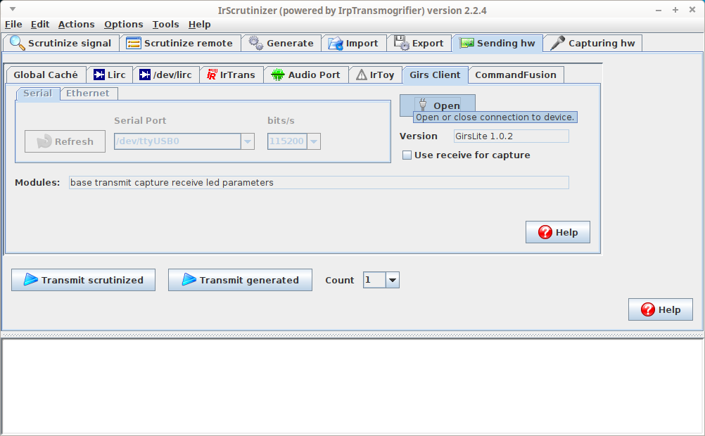
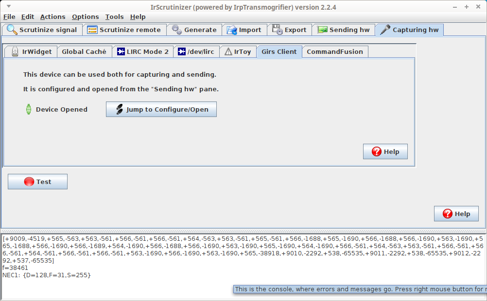
First open the device for sending: Select the Sending hw -> Girs client pane. Select "Serial" and then the appropriate serial port. If the board has been connected after the program was started, it may be necessary to press the "Refresh" button to see the port in the pull-down menu. Press "Open". (This probably causes a reset of the board, causing all the LEDs to go on. If this does not happen, it is not a problem either.) The version of the firmware should now be reported in the field to the right of the "Open" button. The red LED should come on to signal that the board is waiting for a command. The checkbox "Use receive for capture" makes IrScrutinizer use the demodulating sensor for captures. This leads normally to inferior results, and should be used only if, e.g., the non-demodulating sensor is missing.
For receiving, select the board by selecting "Capturing hw. -> Girs Client. Then press the "Test" button, (the red LED should now go out and the yellow go on) and, using any IR remote, fire a command at the (non-demodulating) sensor. The measured frequency and the recorded timings should now be printed to the console. Hopefully, there is also a decode.
For more verbose logging of the communication between the program and the Arduino, select Options -> verbose. (Please do so before searching help.)
Use in Lirc
Since some time (since release version 0.9.4), the Girs driver is officially included in the Lirc sources. The linked documentation describes in detail how to use the board with Lirc.
...and now?
The easy part is now finished. There is a second part for nerds...
Appendix A. Bill of material
| Quantity | Mfg.# | Manufacturer | Description> |
|---|---|---|---|
| 1 | Arduino Nano 3.x (clone) with mini USB, bare holes | ||
| 1 | SFH 4546 | Osram | Infrared Emitters - High Power Infrared 940nm |
| 1 | SFH 4544 | Osram | Infrared Emitters - High Power Infrared 940nm |
| 1 | TSMP58000 | Vishay | Infrared Receivers IR Receiver Module |
| 1 | TSOP34438 | Vishay | Infrared Receivers IR Sensor IC 38kHz |
| 1 | WP710A10ID5V | Kingbright | Standard LEDs - Through Hole Red 25mcd 625nm 40 deg 5V resistor |
| 1 | WP710A10YD5V | Kingbright | Standard LEDs - Through Hole Yellow 15mcd 588nm 40 deg 5V resistor |
| 1 | WP710A10SGD5V | Kingbright | Standard LEDs - Through Hole Green 25mcd 568nm 40 deg 5V resistor |
| 1 | Resistor - Through Hole 68ohm, 1/4W |
Here is a basket at Mouser, not containing the Arduino Nano board.
Appendix B. Accessing devices in Linux
Linux, being a multi user system by design, protects the devices from access by the "non-authorized". In order to access devices like /dev/ttyUSB0 without being root, the recommended procedure is to include the current user in the appropriate group, in general dialout and/or lock. How this is done differs between the different Linux distributions, but is typically
sudo usermod -aG dialout,lock user
(with current user name substituted for user .
For IrScrutinizer, see also this.